

DESCRIPTION
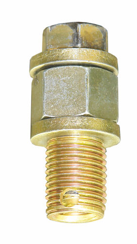
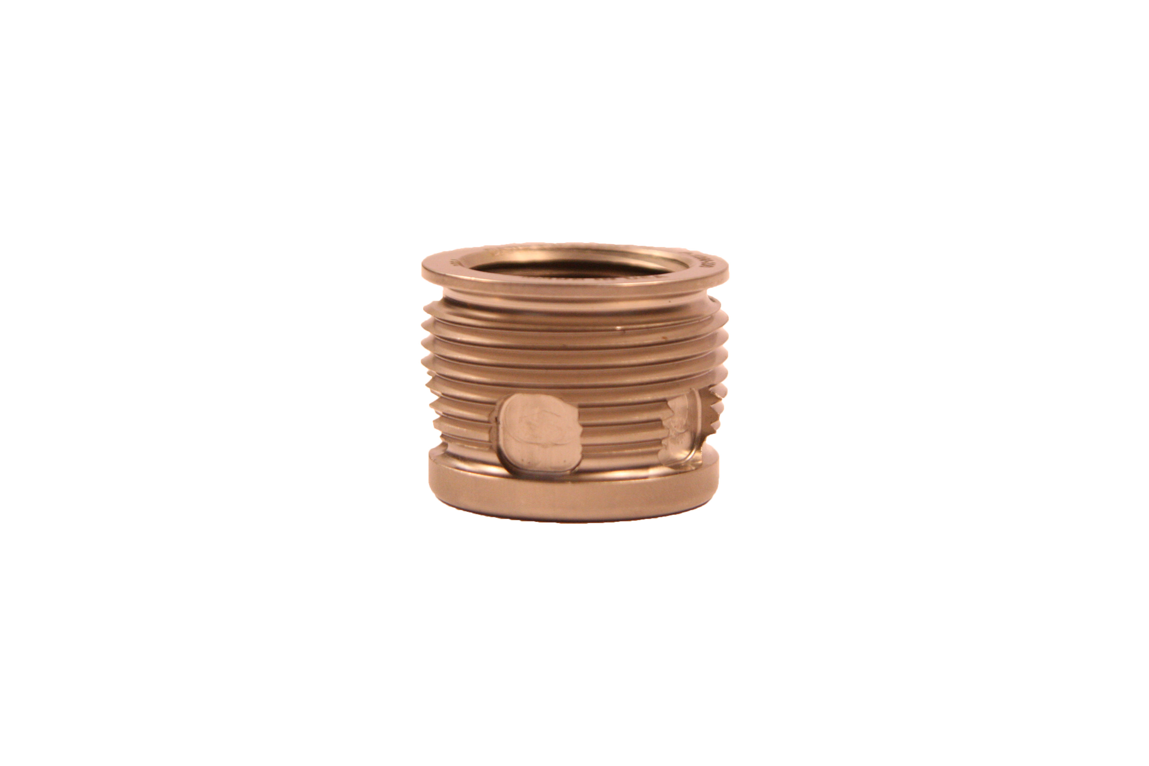
GARD PIPESERT
- Self-Tapping
- Self-Cutting
- Self-Locking
- Won't Pull Out
- Won't Wear Out
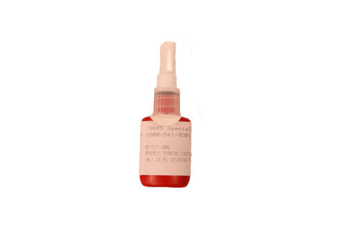
- Note:: Thread Locking Fluid, Part No. 5905-TLF-10ML is included in all kits and assortments
- Note (2):: Special E.M.D. 567/645 Cylinder Head Engine Repair installation tool (Part No. 200M-P800ET) and instructions are available upon request
- Requirement: Important: Thread Locking Fluid, Part No. 5905-TLF-10ML is required and should be ordered seperately when purchasing individual sizes.
- Requirement (2): Be sure to use high-strength cap screw for installation
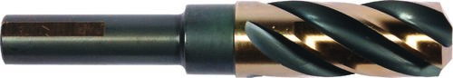
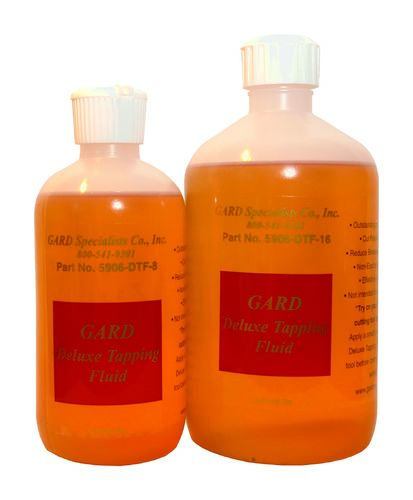
- Installation: You will need: the appropriate DRILL BIT, GARD PIPESERT™ Installation Tool for the PIPESERT™ and a bottle of Thread Locking Fluid PART NO. 5905-TLF-10ML. 1) Drill out damaged threads with the appropriate drill bit. 2) Assemble the PIPESERT™ Installation tool as follows: Place one (1) hardened flat washer onto the special cap screw; (2) are needed for the 3/8-18 PIPESERT™ Next, place the oversized hex nut onto the assembly Follow with (1) hardened flat washer Apply a lubricant (such as GARD Deluxe Tapping Fluid, Part No. 5906-DTF-8, or an anti-seize compound) to the threads of the cap screw, thread the PIPESERT™ on. Make sure that the slot end is first to enter the hole when installing the PIPESERT™. 3) Apply a liberal coating of the Thread Lock Fluid (Part No. 5905-TLF-10ML)* to the outside threads of the PIPESERT™ before installation. Carefully align the PIPESERT™ to the hole. Turn the PIPESERT™ into the hole clockwise using a wrench or socket and impact wrench on the hex head cap screw of the INSTALLATION TOOL. Turn the PIPESERT™ into the work piece until the top of the PIPESERT™ is flush with the top surface of the work piece. *CAUTION! DO NOT SUBSTITUTE THE SUPPLIED THREAD LOCK WITH ANY OTHER COMPOUND 4) When the PIPESERT™ is fully installed, hold the oversize nut stationary and apply reverse torque to the hex head cap screw, allowing the hex head cap screw to rotate out of the PIPESERT™. This allows the tool to disengage from the PIPESERT™. 5) Reverse the PIPESERT™ INSTALLATION TOOL completely from the PIPESERT™ and you have accomplished the repair.Important!ALLOW 24 HOURS CURE TIME FOR THE THREAD LOCK TO SET BEFORE SIBJECTING THE REPAIR TO PRESSURE OR FLUIDS
- Engine Installation: You will need: a 1-3/32” Drill Bit (Part No. 30-175), GARD PIPESERTTM Installation Tool (Part No. 200M-P800ET) for the PIPESERTTM and tube of Thread Lock (supplied with each PIPESERTTM) a 1/2” or greater capacity drill motor and a 1-1/16” open end wrench. 1) Drill out the damaged threads with a 1-3/32” drill bit. 2) Take the PIPESERTTM Installation Tool in hand. Holding it by the sleeve, rotate the stud clockwise so that the cross pin is at its forward position. Thread a PIPESERTTM onto the tool until it stops. The assembly should now look like the one in the drawing above. At this point you are ready for installation. Fig. 1) Insert the Guide Rod B (Part No. 200M-P800ET-ROD) into the port in the Cylinder Head A. Fig. 2) Apply a liberal coating of the Thread Lock supplied with your PIPESERTTM D to the outside threads of the PIPESERTTM D before installation. Carefully align the PIPESERTTM / Insert Tool Assembly C to the hole and Guide Rod B. Fig. 3) Turn the PIPESERTTM D / Installation Tool C assembly into the hole clockwise using a wrench, or socket and impact wrench, on the hex of the stud on the Installation Tool C. Turn the PIPESERTTM D into the hole until the top of the PIPESERTTM D is flush with the top surface of the hole. Fig. 4) When the PIPESERTTM D is fully installed, secure the Sleeve of the Installation Tool C with a 1-1/16” Open end Wrench, and apply reverse torque to the hex drive on the Installation Tool C allowing the Cross Pin to rotate to its reverse position. A gap between the bottom of the Sleeve of the Installation Tool C and the top surface of the PIPESERTTM D is formed, allowing the tool to disengage itself from the PIPESERTTM D. Fig. 5) Withdraw the wrench and un-thread the Installation Tool C completely from the PIPESERTTM D. Fig. 6) Remove the Guide Rod B from the port Cylinder Head A and you have accomplished the repair. IMPORTANT: Please allow 24 hours cure time for the thread lock to set before subjecting to pressures or fluids.
- Size: Pipe Thread
- Length(In Inches): 0.944
- External Diamterer and Threads Per Inch: 1/2-14
- Material: Hardened Stainless Steel
- Wall: Standard
- Tool to Install: 200M-P800T
- Outside Diamter (Inches): 1-1/8
- Installation Tool: 200M-P800T
- Torque Values MM: 72-82
- Torque Values FT.LB: 55-60
- Drill Size: 1-3/32" (Part No. 30-175
FEATURES
- Material Hardened Stainless Steel
- Wall Standard
- Length(In Inches) 0.944
- Size Pipe Thread
- Tool to Install 200M-P800T
- Outside Diamter (Inches) 1-1/8
- Installation Tool 200M-P800T
- Torque Values MM 72-82
- Torque Values FT.LB 55-60
- Drill Size 1-3/32" (Part No. 30-175